
Introduction
Welcome to the next chapter of our Arduino busy board journey! In our previous post, we discussed the conceptualization and choices behind selecting inputs and outputs for our interactive board. Today, we dive deeper into the construction, assembling the parts, establishing the power supply, building the Arduino circuit, coding functionalities, and finally, bringing it all together. Let’s embark on this hands-on venture to transform our ideas into a vibrant and engaging play tool for toddlers.

Parts
Let’s take a look at the components that will bring our Arduino-based busy board to life.
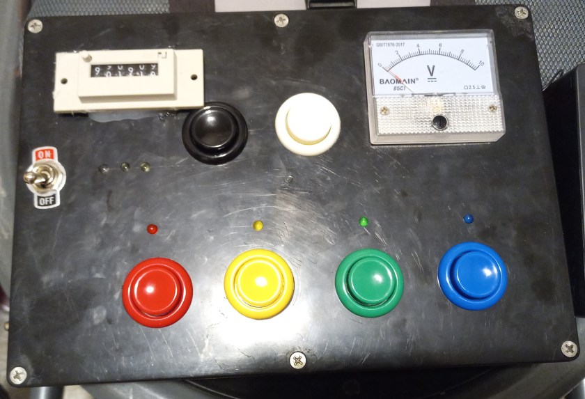
- Enclosure: A sturdy housing to contain and protect the circuitry.
- Colorful Pushbuttons: Interactive arcade-style buttons in various vibrant colors.
- Toggle Switches: Mechanisms to toggle different functionalities.
- 12V AA Battery Pack: Equipped with a built-in power-off switch for convenience and safety.
- Terminal Blocks: Utilized for establishing organized connections for the 12V and 5V buses.
- LED Light Kit with Resistors: An assortment of LEDs with accompanying resistors for illumination.
- Mechanical Counter: A component for counting and interactive engagement.
- Analog Voltmeter: Provides a visual representation of battery voltage.
- Arduino Nano: Provides the means of control for the circuitry.
- 24 AWG Wire: To establish electrical connections and pathways within the circuit. I had used wire that I had laying around, it was solid core wire so that I could use a wire wrap tool instead of having to solder the connections together.

12V Bus
The foundation of our busy board’s power supply is a 12V AA battery pack. This power source serves as the backbone, branching out into various circuits, each catering to a specific interactive component.
Circuit Breakdown:
1. Mechanical Counter & Black Pushbutton
- The first parallel circuit comprises a black pushbutton and a mechanical counter, wired in series. Depressing the pushbutton increments the mechanical counter, adding an engaging counting element to the board.
2. Analog Voltmeter & White Pushbutton
- In the second parallel circuit, a white pushbutton is connected in series with the analog voltmeter. Pressing this button displays the voltage of the battery pack, providing an interactive and informative feature.
3. Toggle Switch & White LEDs with Resistors
- Another branch consists of a toggle switch wired in series with three white LEDs and their respective 470 ohm resistors. Activating the toggle switch illuminates the white LEDs, adding visual stimulation to the busy board.
4. Powering the Arduino Nano
- Lastly, the 12V power source connects to the Vin and GND pins on the Arduino Nano. This provision powers the Arduino, facilitating its functionality within the busy board’s circuitry.
Arduino Circuit
Pushbutton Input Setup:
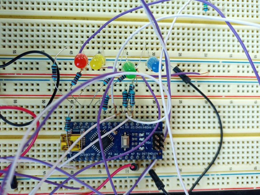
Utilizing the remaining colored pushbuttons—red, yellow, green, and blue—alongside the corresponding LED colors of the same hues, the Arduino circuit enhances interactivity.
- Wiring Pushbuttons:
- The pushbuttons connect to the +5V terminal block on one side and link to specific digital pins on the other side. For instance:
- Blue pushbutton → D2
- Green pushbutton → D3
- Yellow pushbutton → D4
- Red pushbutton → D5
- The pushbuttons connect to the +5V terminal block on one side and link to specific digital pins on the other side. For instance:
- Incorporating Pull-down Resistors:
- To maintain stability, 10K ohm resistors are connected between the digital pins (D2-D5) and the ground, ensuring a stable logic level for each pushbutton input.
LED Output Integration:
For visual feedback, LEDs in matching colors are incorporated.
- Wiring LEDs:
- Each LED is linked to specific digital pins for control:
- Blue LED → D9
- Green LED → D10
- Yellow LED → D11
- Red LED → D12
- Each LED is linked to specific digital pins for control:
- Series Wiring with Resistors:
- Wiring the LEDs in series with corresponding 330 ohm resistors ensures proper current limiting and protects the Arduino pins.
Code
The provided Arduino code is designed to interface pushbuttons with LEDs, creating a responsive interaction between inputs and outputs.
//Define the LED pins

#define BLUELEDPIN 9

#define GREENLEDPIN 10

#define YELLOWLEDPIN 11

#define REDLEDPIN 12


//Define the pushbutton pins.

#define BLUEBUTTON 2

#define GREENBUTTON 3

#define YELLOWBUTTON 4

#define REDBUTTON 5

#define ADVANCEDSWITCH 13


void setup() {

  //Set the pinmode for the led's and pushbuttons.

  pinMode(BLUELEDPIN, OUTPUT);

  pinMode(GREENLEDPIN, OUTPUT);

  pinMode(YELLOWLEDPIN, OUTPUT);

  pinMode(REDLEDPIN, OUTPUT);


  pinMode(BLUEBUTTON, INPUT);

  pinMode(GREENBUTTON, INPUT);

  pinMode(YELLOWBUTTON, INPUT);

  pinMode(REDBUTTON, INPUT);

  pinMode(ADVANCEDSWITCH, INPUT);


  //Run a quick test to make sure all the LED'S light up in sequence.

  digitalWrite(BLUELEDPIN, HIGH);

  delay(300);

  digitalWrite(BLUELEDPIN, LOW);

  digitalWrite(GREENLEDPIN, HIGH);

  delay(300);

  digitalWrite(GREENLEDPIN, LOW);

  digitalWrite(YELLOWLEDPIN, HIGH);

  delay(300);

  digitalWrite(YELLOWLEDPIN, LOW);

  digitalWrite(REDLEDPIN, HIGH);

  delay(300);

  digitalWrite(REDLEDPIN,LOW);


}


void loop() {

  //Check if the pushbuttons for the corresponding color is pushed. If so then make the corresponding LED turn on.

  if(digitalRead(BLUEBUTTON) == HIGH){

    digitalWrite(BLUELEDPIN, HIGH);

  }

  if(digitalRead(BLUEBUTTON) == LOW){

    digitalWrite(BLUELEDPIN, LOW);

  }


  if(digitalRead(GREENBUTTON) == HIGH){

    digitalWrite(GREENLEDPIN, HIGH);

  }

  if(digitalRead(GREENBUTTON) == LOW){

    digitalWrite(GREENLEDPIN, LOW);

  }


  if(digitalRead(YELLOWBUTTON) == HIGH){

    digitalWrite(YELLOWLEDPIN, HIGH);

  }

  if(digitalRead(YELLOWBUTTON) == LOW){

    digitalWrite(YELLOWLEDPIN, LOW);

  }


  if(digitalRead(REDBUTTON) == HIGH){

    digitalWrite(REDLEDPIN, HIGH);

  }

  if(digitalRead(REDBUTTON) == LOW){

    digitalWrite(REDLEDPIN, LOW);

  }

}
Explanation:
- Setup Function:
- Sets the pin modes for LEDs as output and pushbuttons as input.
- Conducts a sequential test to confirm the LEDs’ functionality and proper wiring.
- Loop Function:
- Monitors the state of each pushbutton.
- If a pushbutton is pressed, the corresponding LED lights up; when released, the LED turns off.
The code snippet demonstrates a fundamental setup for linking pushbutton inputs to LED outputs on an Arduino board.

Conclusion
Creating an Arduino-based busy board provides a unique opportunity to blend fun and learning for toddlers. With this project, we’ve integrated various inputs like colorful pushbuttons and toggle switches, coupled with outputs such as LEDs, an analog voltmeter, and a mechanical counter, into an interactive and engaging board.
By utilizing simple hardware components and Arduino coding, this project not only entertains but also introduces basic electronic concepts in an accessible way. The amalgamation of colorful buttons, lights, and interactive elements fosters a stimulating environment for toddlers to explore and learn.
This busy board is not only a homemade entertainment tool but also a platform to introduce early concepts of cause-and-effect, colors, and interactivity. The possibilities to expand and customize this project are endless, encouraging further exploration and creativity.
Building this busy board was an exciting journey, combining creativity, technical skills, and the joy of making something unique for our little ones. It’s a testament to the potential of DIY projects in merging play and education seamlessly.
Stay tuned for more projects and upgrades, and don’t forget to share your own creative endeavors with us on social media!
