
Introduction
Welcome back to the next chapter in our journey to electrify the world of lawn care and landscaping with our electric sleeve hitch project. In Part 1, we delved into the design and components that would power this innovative system. Now, in Part 2, it’s time to roll up our sleeves, get our hands dirty, and take the project from concept to reality.
As we venture into the practical aspects of our project, we’ll guide you through every step of the way. From the circuit to assembling the components, we’re about to witness our vision come to life.
So, grab your toolkit, don your work gloves, and join us as we bring this electric sleeve hitch project to life. It’s a hands-on adventure that promises to elevate your lawn care and landscaping endeavors.
The Circuit
Sleeve Hitch Circuit
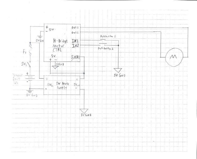
Now that we have our essential components ready, it’s time to roll up our sleeves and dive into the heart of the project—the circuit that will power our electric sleeve hitch system. Below, I’ll describe the wiring process and the connections that bring this project to life.
Automotive Fuse Protection
At the forefront of our circuit lies a 7.5 amp automotive fuse. This crucial component safeguards the entire system, preventing overcurrent and ensuring the safety of our electronics. It connects to the positive terminal of the lawn mower battery before anything else in the system; as shown in the circuit above.
Main Power Switch
To have full control over our system and prevent it from drawing power when not in use, we’ve incorporated a main power switch. This switch enables us to turn the entire system on or off, preserving the battery of our riding lawn mower. This comes directly after the fuse in the circuit diagram above.
Terminal Blocks for 12V
Multiple components in our setup require a 12-volt power supply, including the H-bridge controller and the 12V to 5V power supply. To facilitate these connections, we’ve added a couple of terminal blocks—one for the positive 12 volts and another for the ground (negative) side of the battery. In the circuit diagram above, any where there is a 12v ground symbol there will be a connection to the 12v ground terminal. Also we can see from the circuit that the H-Bridge controller, and the 12V to 5V power supply, need to connect to the +12V of the battery. We will also use a terminal block for these connections.
Terminal Blocks for 5V
As the 12V to 5V power supply will be at the heart of our control system, we’ve included additional terminal blocks for the output of the 5V power supply. One terminal block will handle the positive 5 volts, and the other will manage the ground (negative) side of the 5V power supply. These terminal blocks will serve as the primary connection points for devices that require five volts.
H-Bridge Controller Connections
According to the datasheet of the H-bridge controller, we’ll wire the ENA (Enable A) pin directly to the positive 5V terminal. This connection ensures that the ENA pin is always asserted high, allowing us to use the pushbuttons effectively.
Pushbutton Wiring
The datasheet also guides us in wiring the pushbuttons. They’ll be connected to IN1 and IN2 of the H-bridge controller. On the other side, they’ll be wired to the ground of the 5V power supply. These pushbuttons serve as our control interface, enabling us to raise and lower the linear actuator via the H-bridge controller.
Linear Actuator Connections
Finally, we need to connect the wires of the linear actuator to OUT1 and OUT2 of the H-bridge controller. These connections will allow us to control the linear actuator’s motion using the H-bridge.
The Build
Now that we’re ready to turn our electric sleeve hitch concept into a functional reality, let’s roll up our sleeves and get to work. To bring this project to life, we’ll need a set of essential tools, including a Philips screwdriver, a drill with various drill bits, a multimeter, a soldering iron with solder, a wire stripper, and a crimping tool.
Before we dive into the assembly, let’s take a moment to reflect on the components we introduced in Part 1 of this series. If you missed it, you can catch up here.
Power Wiring

Our journey begins with the main power wiring that connects our system to the 12-volt battery of our garden tractor. Both the positive and negative wires will need fork connectors crimped onto their ends to ensure a secure attachment to the battery terminals.
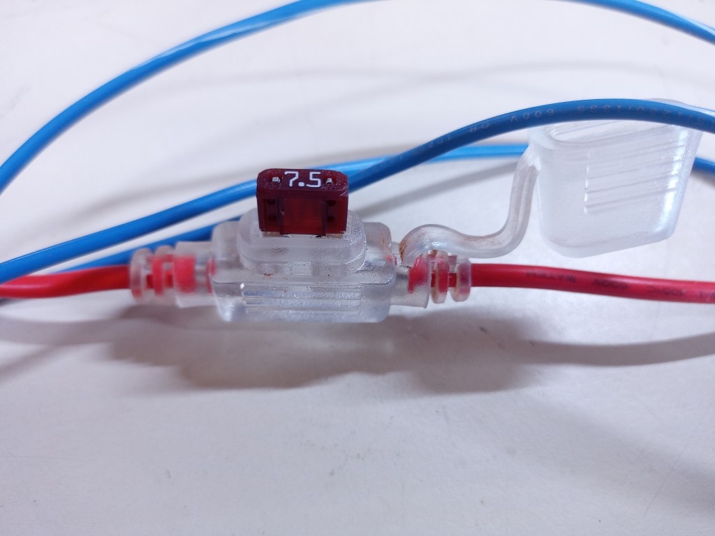
The positive wire will also incorporate an automotive fuse holder, housing a 7.5 amp fuse. This fuse serves as an important safety feature, protecting our system from overcurrent. From the fuse holder, the wire will go to one side of a toggle switch, allowing us to easily turn the system on and off to preserve the battery when it’s not in use.
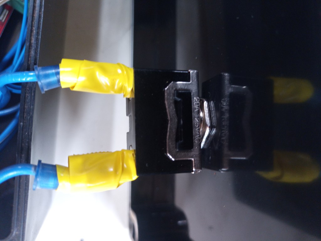
These two wires will then be connected to two terminal blocks—one for the positive 12 volts and the other for the 12-volt ground (negative). From these terminal blocks, we’ll distribute power to both the H-bridge controller and the 12-volt to 5-volt power supply.
Note: Verify Polarities


It’s absolutely crucial to double-check and ensure that you get the polarities correct. Refer to the markings on the boards or consult the datasheets to prevent any potential issues.
Power Distribution


To achieve this, we’ll need two sets of positive and negative wires, each equipped with spade connectors crimped onto one end for easy insertion into the positive and negative terminal blocks. The other ends will be wire-cut to the appropriate length to fit into the screw terminals of the H-bridge controller and the 12V to 5V power supply.
Control Wiring


For control wiring on the H-bridge controller, two wires are required: one going from the +5V pin to the +5V terminal block, and another from the 5V GND pin to the 5V ground terminal block. Additionally, the ENA pin on the H-bridge controller should be wired to the +5V terminal block, ensuring it’s always activated.
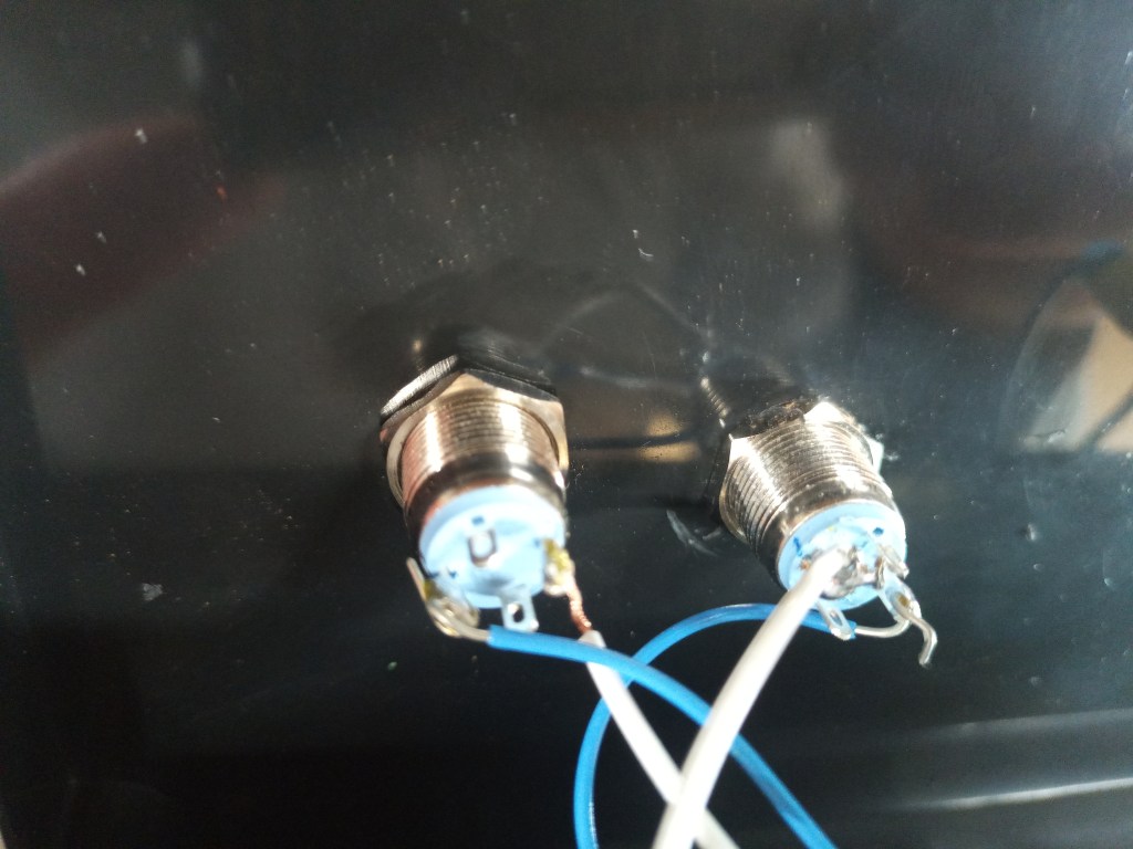
Now, let’s move on to the pushbuttons. Wires will need to be soldered to both of them. The first pushbutton will have one wire connected to IN1 and the other to the 5V GND terminal. The second pushbutton will have one wire connected to IN2 and the other to the 5V GND terminal.
Lastly, the electric actuator wires will be connected to the terminal block on the H-bridge controller, labeled OUT1 and OUT2. The order doesn’t matter, as they can be swapped later to reverse the motor’s direction using the pushbuttons.
| IN1 | IN2 | ENA1 | OUT1,OUT2 |
| 0 | 0 | X | Brake |
| 1 | 1 | X | Floating |
| 1 | 0 | PWM | Forward to PWM Speed |
| 0 | 1 | PWM | Reverse to PWM Speed |
| 1 | 0 | 1 | Full speed forward |
| 0 | 1 | 1 | Full speed reverse |
Assembling the Terminal Blocks
Before we proceed, it’s important to note that all four terminal blocks need a busbar, typically provided in the kit from the link in the previous post, placed into the top of each terminal block. This allows us to utilize the rest of the terminals on each block effectively.
Final Assembly
With the power and control wiring in place, the next step is to drill holes in the enclosure to accommodate the power wires, linear actuator wires, pushbuttons, and the main power switch. Once this is done, it’s time to assemble the components within the enclosure.
Conclusion
And there you have it—a comprehensive journey through the heart of our electric sleeve hitch project. From the conceptualization of a more efficient and user-friendly sleeve hitch to the practical steps of bringing it to life, we’ve covered a lot of ground in this adventure.
As we’ve rolled up our sleeves and delved into the intricate circuitry that powers this system, we’ve seen how every connection and component plays a crucial role in making our vision a reality. The automotive fuse, main power switch, terminal blocks, and control wiring all come together to form a functional and reliable electric sleeve hitch.
The assembly process, guided by the essential tools and meticulous attention to detail, ensures that our system is not just a concept but a tangible solution to enhance your lawn care and landscaping endeavors. With every wire connected, every component secured, and every circuit tested, we’re one step closer to revolutionizing the way you work with your garden tractor.
Part 2 has been an electrifying chapter in our journey, and we hope you’re as excited as we are to see the transformation unfold. In the upcoming Part 3, we’ll take the final leap as we attach this electric linear actuator to our garden tractor’s sleeve hitch, put it to the test, and share our thoughts on the results.
Stay tuned for the next installment, where we’ll witness our project in action and explore the real-world benefits it brings to your outdoor tasks. Together, we’re paving the way for a smarter, more efficient, and more enjoyable approach to lawn care and landscaping.
We invite you to join us on this journey and be part of the innovation. Share your thoughts, questions, and experiences with us as we electrify the world of lawn care. Connect with us on social media, and let’s continue to grow and learn together.
Until next time, keep your tools sharp and your ideas innovative!

2 thoughts on “From Mowing to Plowing: Maximizing Your Lawn Mowers Utility Part 2”