
Introduction
Welcome to a thrilling chapter in our journey of innovation and utility enhancement for riding lawn mowers. Today, we dive headfirst into the realm of circuitry and control systems as we embark on the electrifying mission to design an electric sleeve hitch for your trusty mower.
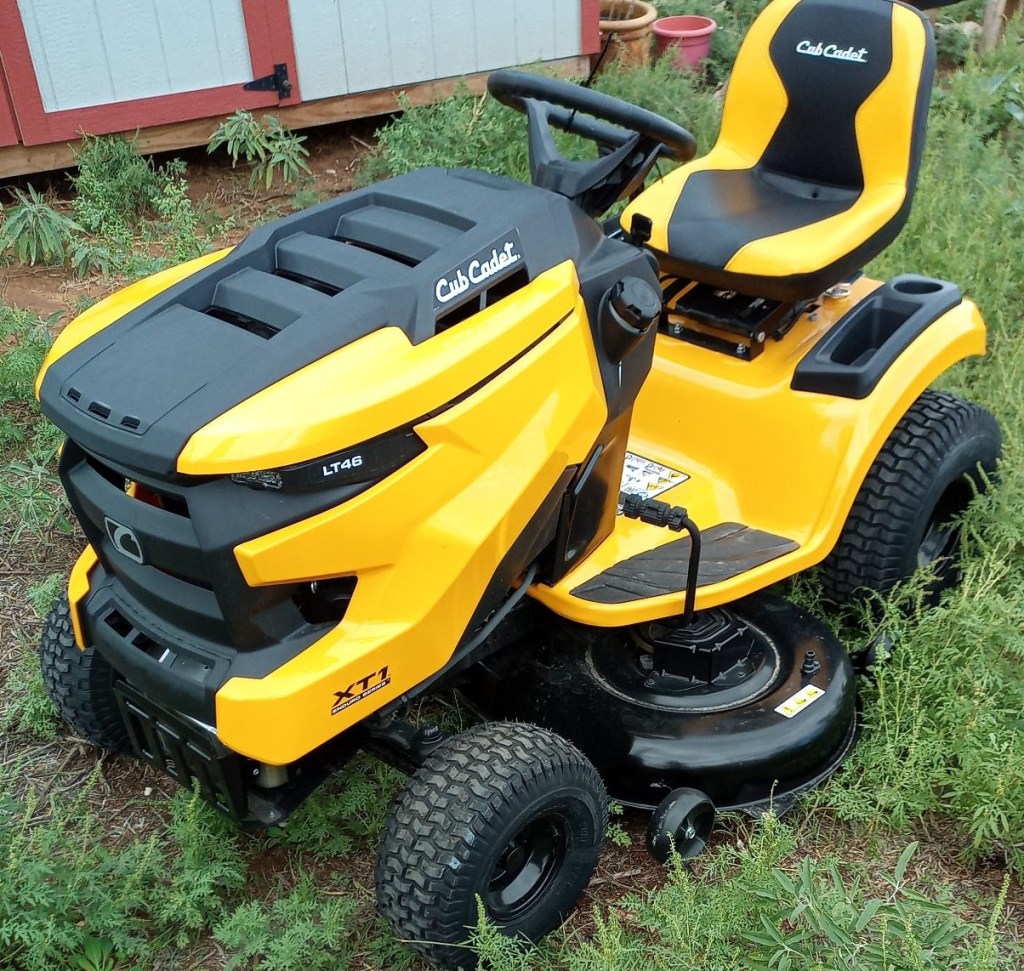
Some of you may be wondering what a sleeve hitch even is. Well, in essence, it’s a remarkable attachment designed to enhance the capabilities of your garden or lawn tractor. This nifty device turns your trusty mower into a versatile workhorse, allowing it to tackle various ground-engaging tasks with ease.
Picture this: you have a garden tractor, and you’re eager to take on a range of outdoor projects, from plowing fields and tilling soil to grading driveways and maintaining your lawn. That’s where the sleeve hitch comes into play. It’s a clever contraption that attaches to the back of your tractor, and it’s designed for versatility.
Traditionally, sleeve hitches are manually operated, often featuring a lever or handle on the tractor. This manual control lets you raise and lower the attachments as needed. It’s a simple yet effective system that greatly enhances your tractor’s utility.
But here’s where our journey takes a twist. The inspiration for this project came when I realized that, despite the utility of sleeve hitches, their manual operation could be somewhat limiting. We needed to make this vital component more user-friendly, efficient, and accessible to all. The answer was clear: we needed to craft an electric solution that would seamlessly integrate with the existing riding mower, allowing for effortless control of sleeve hitch attachments. And so, the journey began.
So, grab your toolkit and join us on this electrifying journey as we transform a traditional manual sleeve hitch into a modern, efficient, and user-friendly electric marvel. Together, we’ll innovate, design, and craft a solution that simplifies your lawn care routines and leaves you with more time to enjoy your outdoor oasis.
In this first installment, we’ll dive into the initial stages of planning, and parts selection, setting the stage for the electrifying transformation that awaits. Let’s get started!
The Design
In our quest to revolutionize the functionality of our riding lawn mower, we found ourselves at the heart of the project—designing an electric sleeve hitch that could seamlessly attach to the lawn tractor and make lawn care and landscaping tasks a breeze. In this section, we’ll unravel the intricacies of the design process that brought our vision to life.

From Inspiration to Blueprint
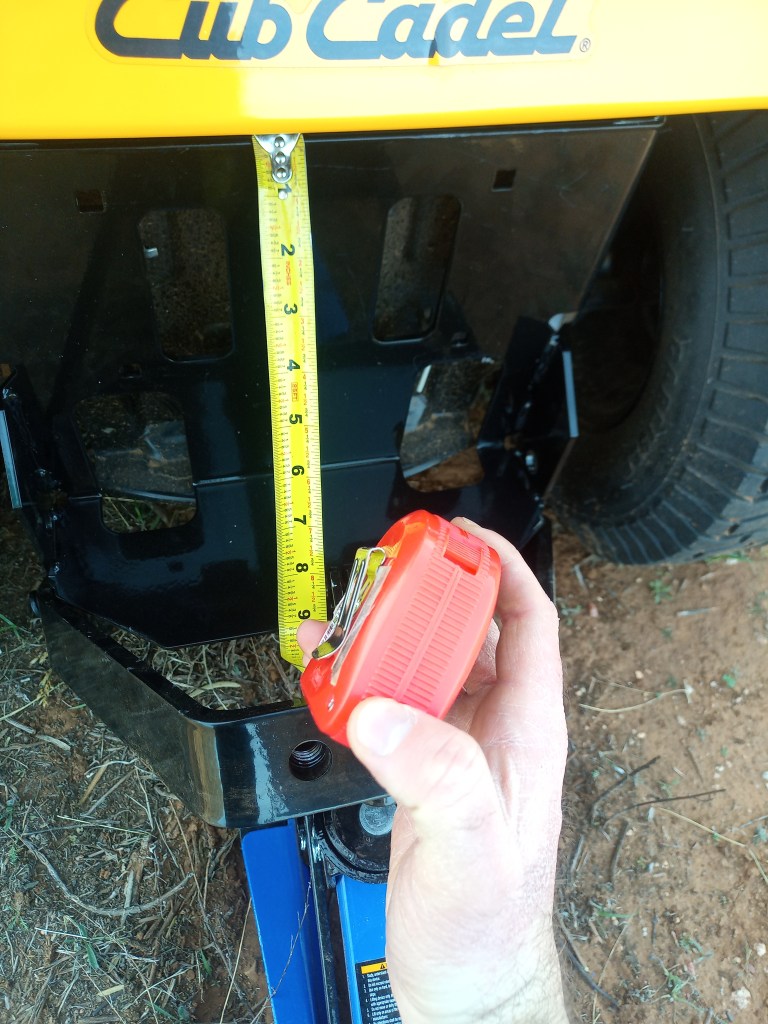
As we embarked on this journey, we knew that our first step was to gather the essential details. The dimensions of the linear actuator needed to be just right to accommodate the sleeve hitch for our lawn tractor. After careful consideration, we settled on a range from 9 inches to 16 inches—a versatile choice that would meet our needs. It does not have to be exact just close enough to this.
The Weighty Matter
Understanding the weight-bearing capacity of our linear actuator was crucial. With attachments potentially tipping the scales at over 100 pounds, we needed an actuator that could handle the load with ease. A robust linear actuator became a non-negotiable component, ensuring that our electric sleeve hitch would be up to the task.
Powering Up
Given that our power source would be the 12-volt battery of the riding lawn mower, we had to select a linear actuator compatible with this voltage. The actuator had to not only operate efficiently within this power range but also deliver the strength needed to lift heavy attachments effortlessly.
Mastering Control
Controlling the linear actuator was the next puzzle to solve. We needed a mechanism that would allow us to effortlessly raise and lower the hitch with the push of a button. Enter the H-bridge controller—a perfect fit for this scenario. Its ability to change the motor’s direction at will meant that our electric sleeve hitch could ascend and descend with ease, granting us precise control over its movement.
Handling Current
A challenge lay ahead with the requirement to handle the current drawn by the linear actuator. The H-bridge controller had to shoulder this load, ensuring a smooth and reliable operation. Finding the right controller capable of handling the power requirements was crucial to the success of our design.
Powering the Control Circuitry
With the H-bridge controller in the picture, we also needed a stable 5-volt power supply to fuel the control circuitry of the H-bridge controller. A 12-volt to 5-volt power supply board became the missing link in our setup, bridging the voltage gap and ensuring seamless communication between our control system and the linear actuator.
With these key design elements in place, our blueprint for an electric sleeve hitch was taking shape. Each decision was carefully considered to ensure that our project would not only meet but exceed our expectations.
The Parts

In case you would like to just go out and grab the parts without reading this section here is a too long didn’t read parts list:
- Linear Actuator
- H-Bridge Controller
- 12V-5V Power Supply
- Buttons
- Switches
- Automotive Fuse Holder with Fuse
- Wires
- Terminal Blocks
- Enlcosure
Now that we’ve outlined the design considerations for our electric sleeve hitch project, let’s take a closer look at the components that will bring this vision to life. Each part has been carefully selected to ensure compatibility, reliability, and efficiency in our setup. Below, you’ll find a list of the essential components, along with brief explanations of why they were chosen:
- Linear Actuator
- Why Chosen: Our choice for the linear actuator was driven by its ability to operate on 12 volts, drawing a modest 3 amps of current. This makes it a perfect match for our riding lawn mower’s battery. Additionally, it boasts an impressive lifting capacity of up to 330 pounds and a 4-inch stroke length. According to the datasheet, it measures 8 inches when fully retracted and 12 inches when fully extended, aligning closely with the parameters we measured earlier.
- Link: On Amazon
- H-Bridge Controller
- Why Chosen: The H-bridge controller was chosen for its versatility. While it’s capable of handling two motors, we only need one for our linear actuator. This controller can manage DC motors up to 10 amps, far surpassing our requirements, as the chosen linear actuator only requires 3 amps.
- Link: On Amazon
- 12V to 5V Power Supply
- Why Chosen: Our riding lawn mower’s battery provides 12 volts, perfectly aligning with the input voltage range of this power supply, which spans from 9 to 36 volts. It ensures a steady 5-volt output at up to 5 amps, providing ample power for our control circuitry.
- Link: On Amazon
- Various Odds, and Ends
- Buttons: These will serve as the control interface, allowing us to raise and lower the actuator. Here are the ones that I used on Amazon
- Power Switch: A master switch will enable us to turn the entire system on or off. Here are the ones that I used on Amazon
- Automotive Fuse Holder with Fuse: This critical component will protect our electronics from overcurrent, ensuring their safety. I had this laying around but here is one that can be found on Amazon
- Wires: We’ll need a selection of wires for connecting and routing various components. I had some wire laying around already but here is some wire that can be found on Amazon
- Terminal Blocks with Crimpable Fork Connectors: These connectors will be placed on the ends of the wires to facilitate secure and reliable connections. Here are the ones that I used on Amazon
- Enclosure: An enclosure will house all of these parts, protecting them from the elements and ensuring a clean, organized installation. Here is the one that I used on Amazon
Each of these components has been carefully chosen to ensure compatibility and reliability in our project. In the upcoming post, we’ll dive into the implementation and wiring process, where you’ll see how these parts come together to create our electric sleeve hitch system.
Conclusion

In this installment of our electric sleeve hitch project, we’ve ventured into the design and components that will shape our vision into reality. We’ve carefully selected each part, and considered the power requirements that will transform our riding lawn mower into an even more versatile tool for lawn care and landscaping.
From the crucial automotive fuse that safeguards our system to the main power switch that puts us in control, we’ve laid the foundation for an efficient and user-friendly electric sleeve hitch. The terminal blocks and 12V to 5V power supply form the backbone of our control system, while the H-bridge controller and pushbuttons give us precise command over the linear actuator’s motion.
In the upcoming Part 2 of this series, we’ll take you along as we design the circuit with the components that we selected. You’ll see how these components come together, and witness the wiring in action. It’s a hands-on journey that promises to electrify your lawn care routines.
But that’s not all—our project doesn’t end here. We’re committed to bringing you more innovative ideas, technical know-how, and engaging content. We invite you to follow us on social media to stay updated on our latest developments, share your thoughts, and connect with a community of like-minded enthusiasts.
Until then, happy mowing, happy innovating, and we’ll see you in the next installment!
